In this Maya Reverse Foot Tutorial you will find the step by step instructions to create a complete reverse foot system. Maya Reverse Foot is uses to create complete and artist friendly rig setup for realistic leg animation. Though this reverse foot system contains a little complexity, but it will be easier with repeated practice.
To follow this Maya Reverse Foot Tutorial you should have a human model in your hand. You also need a complete bone structure to animate it. The following is the image of the model and the skeleton structure from the side view.
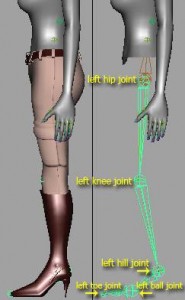
Now, you have to create an IK handle which should be a Rotate Plane IK for the knee. So, use the menu Skeleton > IK Handle Tool. By default the IK Handle Tool containing the Rotate Plane IK system. So, connect from the hip joint to hill joint with a Rotate Plane IK. Now, select and move the IK handle in any direction to see the resulting effect of the IK system.
In this way select the single chain IK solver (ikSCsolver) from the IK Handle Tool settings window. And implement the IK system (ikSCsolver) from hill joint to ball joint and finally ball joint to toe joint.
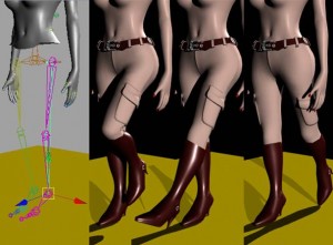
Create new bone-joints for the Reverse Foot system
Now, we have to create the bone structure for the reverse foot lock system. So, select the joint tool using the menu Skeleton > Joint Tool from the Animation menu set. Now, go to the side view and create few joints underneath the left foot joint as the following image. The newly created joints should be named as L_RF_Base, L_RF_Toe, L_RF_Ball and L_RF_Hill respectively. But by default the names are as joint2, joint3, joint4 and joint5. So, we have to rename them. How? Open the Outliner window and double click on every joint and write down the names maintaining the above mentioned naming convention.
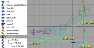
Align new bone-joints (Reverse Foot bone joints) with the existing left foot joints
Now, we have to align the newly created bone-joints perfectly with the existing left foot joints. You can create it easily. How? Just hold down the ‘v’ key on your keyboard and drag a little to align the base joint (RF) with the main left foot Ankle joint. Then drag the left foot base joint (RF) a little down in Y-axis to align with the lowest level of previous bone-joint. Because it is the base joint and should be placed under all joints of the left foot. Now, align other newly created joints or Reverse Foot joints like L_RF_ Toe, L_RF_Ball and L_RF_Hill with the respective main joints. Alternatively you can say that L_RF_Toe should be aligned perfectly with the main L_Toe and so on. Now, open the ‘Outliner’ window and select all Reverse Foot joints at a time either by expanding the joint structure and dragging on them or select one by one by pressing the Shift key. Then change the Radius value to 0.7 in the Channel Box.
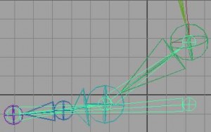
Create control curves to support Reverse Foot
Now, you have to create few control curves to control the Reverse Foot system. You can create these curves using the NURBS menu Create > NURBS Primitives > Circle. So, at first create a curve by dragging on the perspective view after selecting the above mentioned menu. Position it just under the left foot of the model. Scale the NURBS curve or circle so that you can select it easily. Then you have to change the pivot point of the curve because the pivot point should be aligned perfectly with the main left hill joint. You can align the pivot point of the curve easily. Select the curve using the move tool. Then hold down two keys at a time. In this case the first key should be the ‘d’ and the second key is the ‘v’. Now move the cursor pressing the left mouse button towards the left hill joint. The pivot point will be snap aligned with the left hill joint. But, here you have to be careful about the alignment. This control curve should be named ‘Left Foot Control’.
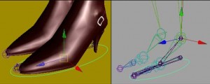
Now, you have to create another two control curves like the ‘Left Toe Control’ and ‘Left Ball Control’. So, create two curves as the following image and align the pivot of those curves one with the Ball and another with the Toe after positioning them perfectly. Then open the ‘Outliner’ window and rename these curves maintaining the protocol. Select all the curves and press Ctrl+g to create a group. Rename the group as ‘L_FootControls’. Create a new layer in the Layer Editor window and name it ‘left_foot_controls’ and change the layer color to yellow. Now, add the controls group in the layer.
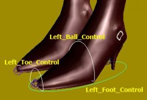
Here, we can find that all the control curves containing the transformation, rotation and scale values. But, we need all control curves with basic values like (0, 0, 0, 0, 0, 0, 1, 1, 1) from transformation to scale respectively. So, expand the controls group and select all curves. Then select the menu Modify > Freeze Transformations. And then delete construction history using the menu Edit > Delete All by Type > History. Now, select and move the L_FootControls group under the ‘body_rig_gr’.
Constraining the curves with the reverse foot system
This part of this Maya Reverse Foot tutorial is very important. Actually, this is the complete rigging procedure for the left foot. Here we have to do few constraining task. At first you have to constrain the L_RF_Base with the L_Foot_Control using the parent constrain method. To do this, select the L_Foot_Control at first and then the L_RF_Base holding the Shift key. Now click on the small-box beside the menu Constrain > Parent. A Parent Constraint window will appear. In this window, click on the menu Edit > Reset Settings to get the default settings. Then click apply and close button. Now, if you select and rotate the L_Foot_Control then the whole Reverse Foot system will rotate with the Parent.

Now, we have to constrain the main joint chain with the Reverse Foot joint chain. After the joining procedure, the left foot control (L_Foot_Control) drives the Reverse Foot joint chain, the Reverse Foot joint chain drives the IK system of the main joint-chain, the IK implemented joint chain drives the main bone structure which will drive the body part. Let’s start the constraining procedure.
Now, at first we have to create a point constraint between the L_RF_Hill and the l_leg_ik_handle. In this case the parent should be the reverse-foot-hill joint which will control the movement of the left IK. To do this point constraint, at first select the L_RF_Hill joint and then the L_leg_ik_handle. Now click on the small-box-icon beside the menu Constrain > Point. The Point Constraint Options window appears. In this window confirm the ‘Maintain Offset’ option and the ‘Constraint Axes’ option is in turned on condition. Then click on the Apply button and finally close this window. Now, if you move the ‘L_Foot_Control’ then you will find the left leg IK will move with it.
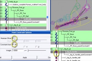
But for the reverse-ball joint a Point constraint isn’t really needed. Because if you create a Point constraint between the reverse-foot-ball joint (L_RF_Ball) and the left-leg-ik-ball-joint (L_leg_ik_handle_ball) then after constraining them you can’t get the proper rotation effect from the reverse ball joint. So, a Parent constraint is good for this reverse ball constraining. So, at first select the L_RF_Ball joint and then the L_Leg_ik_handle_ball. Then click on the small box icon beside the menu Constrain > Parent. The Parent Constraint Options window appears. Here confirm the Maintain Offset, Translate All and Rotate All options are in checked on condition. Now, click on Apply and close the window. If you now select the left-reverse-ball joint (L_RF_Ball) and rotate it then you will get proper rotation effect from this.
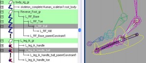
Finally we have to create a constraint between the left-reverse-foot-toe (L_RF_Toe) joint and the left-leg-ik-handle-toe (L_leg_ik_handle_toe). Here this constraint should be an Orient Constraint. So, click on the small box icon beside the menu Constrain > Orient. Here confirm the Maintain Offset and Constraint Axes All both in checked on condition. Now, if you select the reverse-foot-toe joint and rotate it then you will find a natural animation as per your requirement.
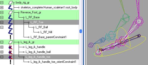
The reverse foot system is now working to support a true foot and leg animation. But, I need to select and manipulate the reverse foot system quickly and easily. But, how can we do this? We have already few control curves to support the reverse foot system. Just constrain these control curves with the reverse foot system. Then they will be useful to control the reverse foot system to animate the leg normally.
So, select the left-ball-control curve (L_Ball_Control) and then the left-reverse-foot-ball joint (L_RF_Ball). Now, create an Orient Constraint between them after confirming the Maintain Offset and Constraint Axes All checked on. Now, if you select the left-leg-ball-control and rotate it then you will find a nice rotation effect.
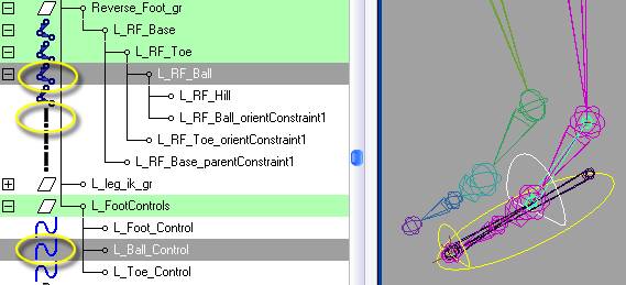
Now, you have to do the same constrain between the left-foot-toe-control curve (L_Toe_Control) and the reverse-foot-toe joint (L_RF_Toe). Then apply the same Orient constraint onto them after confirming the Maintain-Offset and Constraint-Axes-All checked on. Now, if you select the left-foot-toe-control curve and rotate it then you also be able to get the real rotation effect.
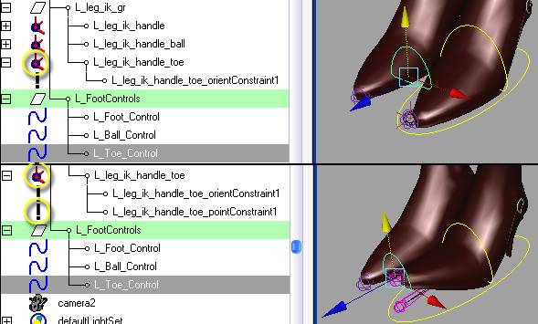
But, if you select the left-foot-toe-control curve and move it then you will not be able to get any movement from the reverse foot joint. But, I think it is required for complete rig setup for the toe. So, select the left-leg-toe-control curve (L_Toe_Control) and the ik-handle for toe (L_leg_ik_handle_toe). Then create a Point Constraint between them. Now, you will be able to get the movement effect from the left-toe-control curve.
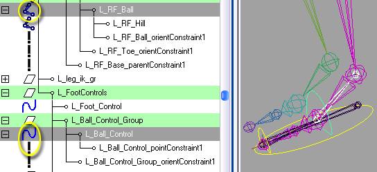
Still we have some task to do. Our aim is to create real reverse foot lock system. So, we need some grouping task. But, in this case the grouping should be done on a single object. Because we need two pivot point of a same control curve for different purposes. We have to create this so that the control can have a pivot point and the group can have a pivot point. Here, both the toe and the ball control curve needs the grouping.
So, at first select the toe control curve and press Ctrl+g to create a group and name the group as ‘L_Toe_Control_Group’. Now, position the pivot point of this group just in the place of the hill joint. To do this, select the group and press Insert button. Now, press and hold the ‘v’ key on the keyboard and move the pivot point. After completion press Insert button once more.

Do the same grouping procedure for the ball control curve. But, here the pivot point should be in place of toe-joint.

Now, we have to do another constraint and that is between the left-toe-control (L_Toe_Control) and the ball-control-group (L_Ball_Control_Group). So, select the L_Toe_Control first and then the L_Ball_Control_Group. Now, create an Orient Constraint with ‘Maintain Offset’ option checked on.

Now, create another constraint between the left-foot-control (Left_Foot_Control) and the left-toe-control-group (L_Toe_Control_Group). Because, we want the left-toe-control should follow the movement of the left-foot-control. So, select the Left_Foot_Control first and then the L_Toe_Control_Group and implement the Parent Constraint between them.

But, still the rig setup with the reverse foot is not completed. Why? Because, the ball-control-curve is not moving with the left-foot-control. So, we have to create another Point constraint between the L_RF_Ball joint and the L_Ball_Control. So, select the L_RF_Ball first and then the L_Ball_Control and implement a Point constraint between them. You have already done this.
 a
a

